Do you need a fuse between solar panel and charge controller?

Do you need a fuse between solar panel and charge controller?
Firstly, you should know that fuse and circuit breakers are used to keep the system wiring from becoming too hot and burning. They are also used to prevent devices from burning or becoming more damaged if there is a short circuit.
One of the most crucial places to install a fuse in your solar panel system is between the solar panel and the charge controller. This lessens the risk of wires overheating and possible system failure. When installing your solar system, the best way to ensure protection is by using fuses at key installation points.
A 12V lead-acid battery is a good example to describe the function of a fuse. A fuse between the battery and the AC/DC Inverter will stop the possibility of an explosion in the event of a short circuit. It will also break the circuit quickly enough to stop the wires from catching fire or becoming dangerously hot. The fuse will safely disable the AC/DC inverter, battery, and wires.
Note: If you’re not sure about this, please consult an electrician! Safety is ensured through the proper use of a fuse.
Do you need a fuse between the solar panel and the charge controller?
The following components are important when fusing your solar system.
Solar Panel Fusing
Commercially produced solar panels with ratings of at least 50 watts are equipped with 10 gauge wires that can handle up to 30 amps of current flow. They can be connected in series, so there is no need to fuse. However, this isn’t the case when you have panels connected in parallel. When connected in parallel, the system’s current is additive.
For instance, if you have four panels that can each handle up to 15 amps, a defect in one panel could draw all 60 amps to the panel that is short-circuited. This can cause the wires that connect to the panel to exceed 30 amps, which could result in the wire pair catching fire. For panels in parallel, a 30 amp fuse is required for each panel. If your panels are less than 50 watts and solely utilize 12 gauge wires, then 20 amp fuses are required.
Combiner/Parallel Box Fusing
A combiner box holds the fuses/breakers of each panel as well as one or more “combined fuse” that connects to the grid-tie inverter or charge controller. Before you can figure out the size of the “combined fuse/breaker,” you must first determine the maximum current that will flow on the panels you have.
If the actual conditions of installation are not in line with the factory ratings for solar panels, the rating could be exceeded. The industry standard is to increase the short circuit current (Isc) by 25% to account for this possibility. The National Electrical Code (NEC) requires that a 25% factor be included if the load is continuous.
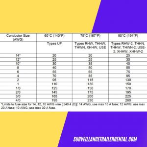
Below is a table that shows the power of wires inside conduits as per the NEC. Note that some wires with the same gauge can handle higher amps and have higher temperatures. An optimum of 8 AWG USE-2 wire sets from the combiner box and charge controller is sufficient to manage 55 amps. To safeguard the wire set it is recommended that a 60-amp fuse or break should be used. This also aligns with the max capacity of the charger you choose.

Amp capacity per NEC standard
Charge Controller and Battery Fuse
When using a Pulse Width Modulated (PWM) charge controller, the “worst-case amps” flowing to and from the controller are the same, so the wire and fuse size should be the same. MPPT charge controllers, on the other hand, have the ability to lower the voltage and increase the current that flows between the controller and the battery bank. So, the exact wire and fuse sizes have to be recalculated according to the charge controller manual. It is recommended that a 60-amp fuse connects the unit and the battery bank to a 50-amp charge controller. Also, choose a wire that is appropriate in rating.
Battery Fuse and Inverter
The fusing and wiring that connects the battery to an AC/DC inverter are of critical importance. This is because it is where the most current is likely to flow to. Similar to the charge controller’s case, the recommended wire and fusing can be found in the manual for the inverter. It is very likely that the inverter already has a built-in fuse/breaker on the input and the output (AC) side of the unit.
For instance, a typical 1500-watt 12V pure sign wave inverter draws up to 125 amp continuously which increases to 156 amps once you add in the NEC continuous-use 25% factor. 1/0 AWG (American Wire Gauge) is the minimum requirement for USE-2 wires. These are the general limits for a welding cable.
- 2/0 AWG 400 amps
- 1/0 AWG 300 amps
- #1 AWG 250 amps
- #2 AWG 200 amps
- #4 AWG 150 amps
Conclusion
This article was merely an introduction. Before a design can be completed, it is essential to consider other aspects like cable length and fuse/breaker types. There are various wire size and fuse calculators online that you could make use of when designing your solar system. If you take your time and use the correct mix of rated components, the system should function properly. With this, you’ll be able to sleep peacefully knowing you engineered it to be a secure and reliable system.
Do you need a fuse between the solar panel and the charge controller? Learn more about fuses, inverters, and other solar components here.


